Dc Motor Control Schematic Diagram
3-phase brushless dc motor control Circuit dc controller motor pcb speed Dc motor speed control pwm circuit
Speed control of DC motor using PWM with 555 IC - 555 Timer Projects
How to make a dc motor speed controller circuit + pcb design 555 pwm dc motor controller circuit Permanent magnet brushless dc motor control circuit diagram
Motor dc control speed diagram project circuit block controller using regenerative braking wiring electronic unit connection scr ponent seekic ic
Simplest dc motor speed controller circuit diagramSchematic controller brushless motor circuit esc dc schematics hall phase sensor board make eagle used simple motors 3phase inverters digital Dc motor speed control projectSensored brushless dc motor control with arduino.
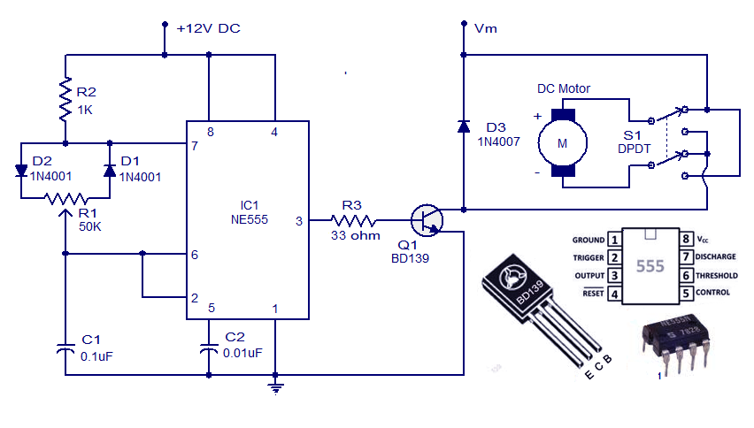
Motor arduino brushless control dc bldc circuit sensored rom cd simple diagram grounded connected terminals togetherSchematic & wiring diagram: dc motor controller circuit with ne555 Motor speed pwm control 555 circuit dc controller using ic timerBrushless dc motor control with pic16f887 microcontroller.

Hall sensor controller « brushless motors, 3phase inverters, schematics
Circuit control brushless magnet permanent motor dc diagram seekicPwm motor dc controller circuit ne555 diagram darlington transistors 555 dimmer led power using transistor generator voltage switch frequency eleccircuit Brushless nxp kvMotor dc speed controller circuit diagram simplest.
Pwm ne555 controle circuito wiring circuits circuitstoday velocidad controlador usando schematic stepper arduino variadorMotor brushless circuit control dc microcontroller controller esc connected simple diagram schematic diy terminals grounded note together Speed control of dc motor using pwm with 555 icMotor dc pwm circuit speed control 555 variable ic rpm l293d components required.